A leading industrial manufacturer approached ARKUS engineering with a critical request: validate whether a welded lifting structure could safely support heavy machinery under demanding safety standards. Early simulation results on the model provided by the client raised red flags, showing stress levels in the welds that far exceeded the material’s allowable limits.
ARKUS applied a structured, engineering-first approach to investigate. By rebuilding the model, refining the mesh, and conducting a focused submodel analysis, we revealed that the apparent stress peaks were artefacts, not indicators of actual structural failure.
The outcome: a validated, reliable lifting assembly — achieved without costly redesigns or project delays. More importantly, the analysis restored confidence with clear, data-backed evidence of structural integrity. In this case, the true engineering challenge wasn’t a flawed design, but recognising when the simulation data was misleading. ARKUS brought clarity to a situation that could easily have led to unnecessary rework, added cost, and avoidable delays.
The Challenge
The client needed to ensure that a welded lifting assembly could safely handle the weight of heavy industrial equipment, without risk and guesswork. The design featured a base plate with four welded lifting lugs, each required to carry a significant share of the load. To meet safety standards, a factor of four was applied, pushing the effective load to nearly 20 kN per lifting point.
The chosen material, 1.4301 stainless steel, is known for its good weldability, reliable strength, and corrosion resistance. However, early finite element method (FEM) simulations raised concerns. The results showed extreme stress levels—some exceeding 4,000 MPa—far beyond what the material should ever experience.
These numbers didn’t add up; they appeared too extreme to be credible. ARKUS suspected the issue wasn’t the design itself, but how it was being represented in the model.
The Root Cause: Modelling Artefacts
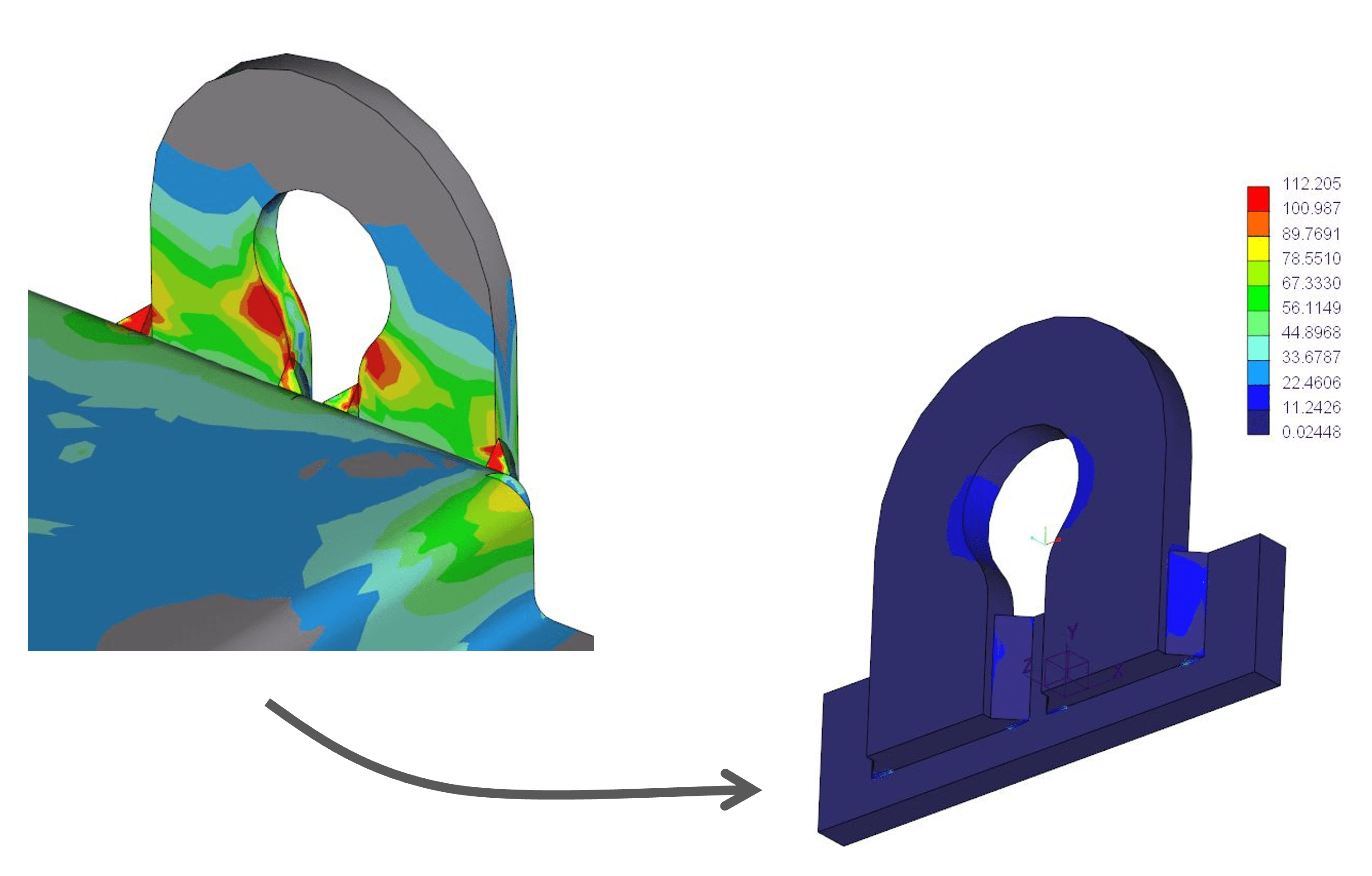
A closer look at the simulation revealed the likely culprit: modelling artefacts. The original CAD model included overlapping geometries, tightly bent edges, and complex weld transitions—all of which made accurate meshing difficult. These details created distortions in the finite element mesh, leading to exaggerated stress peaks that didn’t reflect real-world behaviour.
If left uncorrected, these artefacts could have led to a false conclusion: that the structure was unsafe. ARKUS quickly identified the issue and proposed a more reliable two-step strategy to uncover the actual performance of the lifting system.
Step One: Rebuilding the Full Model
The first step involved reconstructing the base plate geometry to eliminate problematic overlaps and create clean, meshable transitions. Overlapping contact areas were adjusted to introduce small but critical gaps, improving mesh behaviour and removing unnecessary geometric complexity. Weld transitions were also simplified, helping eliminate sharp corners and undefined interfaces that often cause stress anomalies in simulations.
The meshing strategy was refined to suit the updated geometry. An adaptive global mesh was maintained to balance accuracy and computational efficiency. At the same time, the weld regions were assigned a local mesh resolution of 1 mm to capture steep stress gradients with precision.
To ensure realistic load paths, welds were explicitly modelled with a 5 mm throat thickness, in line with DIN EN ISO 2553, and were connected using bonded interfaces. This setup guaranteed that forces transferred directly through the welds—exactly as they would in the physical assembly.
The improved full-model simulation delivered more consistent results. Stress levels dropped noticeably, and the distribution followed a logical load path. While some local concentrations remained—especially near the ends of the welds—the analysis now reflected a plausible structural response. Still, the complexity of the full system meant some uncertainty lingered.
Step Two: Isolated Submodel Analysis
To remove any remaining uncertainty, ARKUS developed a focused submodel that isolated a single lifting lug and a portion of the base plate. This targeted approach allowed for a cleaner, more controlled assessment of how the welds performed under load.
The simplified geometry featured a 10 mm-thick base plate reinforced with two 40 mm gussets, replicating the actual support conditions. A load of 19,620 N—representing the full system weight with the safety factor applied—was directed into the inner contour of the lug, simulating how a shackle or hook would engage during lifting. The rear face of the plate was fixed to replicate a constrained support surface.
As in the full model, the welds were represented as physical volumes with a defined 5 mm throat thickness and connected via bonded interfaces. The mesh was finely refined around the weld zones to capture the stress flow with precision.
This streamlined setup eliminated distractions from unrelated geometry and enabled ARKUS to focus purely on the structural behaviour of the welded connection.
The Results
The submodel analysis provided a clear and credible view of how the welded connection performed under conservative loading conditions. The results confirmed that the design was structurally sound.
Stress distribution was smooth and followed expected load paths. Localized peaks were observed near the weld transitions—typical of sharp geometry—but were well within acceptable limits. The welds carried the load effectively, without signs of overloading or instability.
Restored Confidence and a Clear Path Forward
The analysis did more than verify numbers—it resolved uncertainty, strengthened the case for production, and reaffirmed trust in the design. Here’s how:
Validated Safety Under Real-World Conditions
The submodel confirmed that the welded joints could safely carry the required loads, even under conservative assumptions. Stress values stayed within the elastic range of the material, with no signs of structural weakness.
Avoided a Costly Redesign
By identifying the root cause of the stress anomalies, ARKUS helped the client avoid unnecessary design changes, material use, and delays. The original design was proven sound, saving both time and cost.
Provided Clear, Credible Documentation
The simulation results were delivered in a transparent, structured report that supported internal quality assurance and approval processes. This gave stakeholders confidence in the product without requiring additional testing.
Reduced Risk and Uncertainty
What started as a potential failure case turned into a demonstration of robustness. ARKUS helped eliminate false alarms caused by modelling artefacts, giving the client a clear path forward.
Engineering Clarity Where It Matters Most
What made the difference with this project was a clear, focused process. By breaking the problem into manageable parts, refining the model, and applying practical judgement, ARKUS turned what looked like a critical issue into a resolved design, ready for production.
The takeaway? Real-world engineering problems are rarely solved by software alone. They require a team that understands when to challenge the data, how to simplify complexity, and where to focus attention for the highest impact.
This is the approach ARKUS brings to every project—combining experience, precision, and practical thinking to deliver solutions that work.
From Uncertainty to Execution
Projects like this demonstrate the value of working with a partner that understands both the science and the strategy of engineering. ARKUS doesn’t just produce simulations—it produces decisions you can trust.
At ARKUS, that’s the standard. Whether solving complex mechanical problems or validating critical systems, we bring structure, focus, and real-world thinking to every project, turning ideas into solutions that are ready to perform.
Need Clarity on a Critical Design?
Partner with ARKUS engineering to validate, refine, and deliver solutions that are built to perform—no guesswork, just results. Contact us to start your next project with confidence.